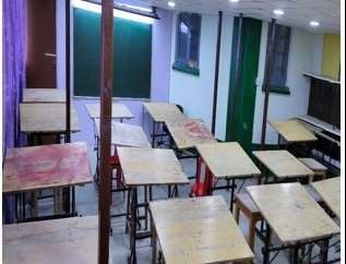
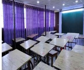
ENGINEERING GRAPHICS AND MACHINE DRAWING LABORATORY
Lab In-Charge (Engineering Graphics): Dr. Kirti
Tewari
Lab In-Charge (Machine Drawing)): Dr. Sudip
Banerjee
This course is designed to introduce the students to the “universal language of Engineers” for effective communication through drafting exercises of geometrical solids. To learn the technical drawing is an important part of the engineering profession. The objective of the course is to teach students to communicate using graphic techniques. Technical Graphics is used to communicate the necessary technical information required for manufacture and assembly of machine components. These drawings follow rules laid down in national and International Organizations for Standards (ISO). Hence the knowledge of the different standards is very essential. Students have to be familiar with industrial drafting practices and thorough understanding of production drawings to make themselves fit in industries.
Course Objectives- To create awareness and emphasize the need for Engineering Graphics in all the branches of engineering.
- To follow basic drawing standards and conventions.
- To develop skills in three-dimensional visualization of engineering component.
- To understand and apply national and international standards while drawing machine component.
- To understand the concept of various tolerances and fits used for component design
- To familiarize in drawing assembly, orthographic and sectional views of various machine components
- Upon completion of this courses the student will able to demonstrate the knowledge and ability to:
- Understand the importance of ISO Standards, Lettering and Dimensioning in Engineering Drawing
- Graphically construct and understand the importance of mathematical curves in Engineering applications Solve specific geometrical problems in plane geometry involving lines, plane figures and special Curves.
- Interpret Orthographic, Isometric and Perspective views of objects. Draw sections of solids and development of surfaces including cylinders, cones, prisms and pyramids.
- Visualize geometrical solids in 3D space through exercises in Orthographic Projections Produce orthographic projection of engineering components working from pictorial drawings
- Identify the national and international standards pertaining to machine drawing.
- Apply limits and tolerances to assemblies and choose appropriate fits.
- Recognize machining and surface finish symbols.
- Explain the functional and manufacturing datum. CO5 Illustrate various machine components through drawings.
Engineering Graphics (1st Year 1st Semester Course for All Departments)
- Introduction: Overview of the course, Examination and Evaluation patterns. Lines Lettering and Dimensioning: Types of lines, Copying, Lettering, Dimensioning,
- Geometrical Construction: Polygons, Scales, and Engineering Curves.
- Orthographic projection: Principles of Orthographic projection, Projections of points, Straight
- Lines and traces, Projections of Laminas, Projections of Solids
- Development of Surfaces: Draw the development of surfaces for Prisms, Cylinders, Pyramids and Cones.
- Section of Solids: Sectional planes, Sectional views - Prism, pyramid, cylinder and cone, true shape of the section. Development of truncated objects.
- Isometric views: Isometric axis, Isometric Planes, Isometric View, Isometric projection, Isometric views.
Machine Drawing (2nd Year 3rd Semester Course for ME Dept)
- Introduction: Representation of elements of machine drawing: Engineering Materials, Surface finishes, tolerances, sectional views, Screw threads.
- Component Drawings: Bolts and Nuts, Locking devices, Keys and Cotter joints, Knuckle Joint, Riveted joints, Shaft Couplings, Bearings and Pipe joints.
- Assembly Drawing Practice: Draw the assembly drawings of Stuffing Box, Pedestal Bearing using the component drawings. Machine drawing practice using AutoCAD.

